By Telefónica R&D Chile.
This tutorial will be divided into parts for easier reading and practical purposes.
1. Introduction to the technologies used
2. Hardware configuration
3. Arduino, software and communications
4. Orion Context Broker (FIWARE)
5. Action from a remote web
The idea of this tutorial is to learn some theoretical concepts and quickly apply them in practice. Possibly, when you finish this tutorial, you will have imagined hundreds of alternatives based on the original concept to create a sensor-based solution connected to the Internet (basic principle of the Internet of Things).
Come on, let’s get started!
Introduction to the technologies used
Before we start, it’s important to briefly review and understand some key concepts. If you are familiar with these concepts, you can proceed directly to the next section.
First of all, the Internet of Things corresponds to the third great wave in computer technology. The first wave was the development of computers in the 60s, then the use and exploitation of the Internet, with mass penetration starting in the eighties, and now the IoT. But what is the Internet of things?
To answer the question above, we must understand the concept of ‘connected things’ whereby electronic devices can send and receive information via the Internet. Examples including home thermostats, smart cars, entry controls and a thousand other devices. But the reader might be wondering why these devices should be connected to the Internet.
Primarily because the data obtained from these devices can later be combined with other data to obtain more advanced functionalities. Imagine you set your smartphone alarm to wake you up in the morning. It’s winter so there is not much light when you wake up. At the sound of the alarm, soft lighting is activated, the toaster starts to warm your bread and the coffee begins to heat up. This may be a rather elementary example, but it helps us to understand that the more information we have and can interrelate, the more devices we can actually create to help improve our quality of life.
One interesting point to discuss is the use of standards. For the specific case we will review later in Orion Context Broker section, an adaptation based on the OMA (Open Mobile Alliance) NGSI (Next Generation Service Interface) specification is used. In simple terms, this means that the HTTP requests or actions to be used are those that are currently employed by browsers such as GET, POST, DELETE and PUT to interact with the Context Broker.
We have reached the end of part one of this tutorial, so let’s get started with the practical information.
Hardware configuration
This is now the practical part of tutorial, so let’s get started!
The components we will be using are:
- An Arduino Board (there are many alternatives, but a version with WiFi is essential)
- A breadboard
- LEDs
- Connecting cables
- A router or a cellular device that can deliver WiFi (tethering)
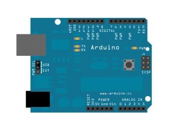
As a brief introduction to Arduino, it should be highlighted that this hardware is based on an Open-Source specification that, using a board with a microcontroller, allows interaction with numerous devices such as sensors, lights, switches, etc.
Arduino has its own interface development using the C ++ language and integrates a number of libraries to facilitate the  implementation of prototypes. This does not mean that Arduino cannot be used in industrial or high-demand environments. However, in these scenarios cost issues usually lead to the use of ad-hoc components.
When observing the structure, you can recognize some digital pins on the top and analogue pins at the bottom. Also, at the bottom, is the row of connectors to power a testing board or breadboard. The board also must have a connector to an electrical outlet and a USB mini connector, among other components, depending on the version of the board and if you use add-on ‘shields’ or not.
If we connect a LED to the board we can do so directly, connecting the LED to digital pin 13 and the GND as seen here. Although it should be noted that the digital pin 13 comes with a resistor, so it would be unnecessary in the image below. (In other pins resistors must be installed) .
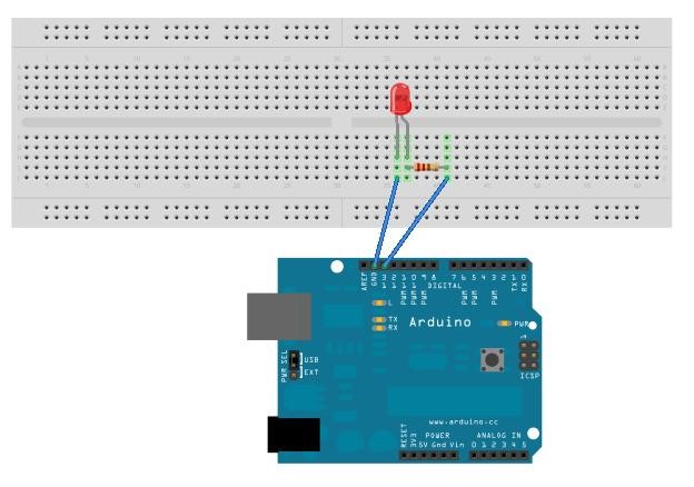
Lastly, the same result can be obtained using a breadboard. This is a good idea if you want to add more LEDs or sensors to our Arduino board so you can add more functionalities. Remember that on a breadboard power runs horizontally in the outer points and vertically in the inner points. So the result is:
Take note: Specifically, the Intel Edison Arduino board requires 2 Micro USB cables and a power connection.
Hard to understand? I hope not. This concludes part two of our tutorial.
Arduino, software and communications
In this tutorial we will learn how to program the Arduino board so as to turn the LED we installed in part two on and off. Then, we’ll use an internet connection with the board’s WIFI.
As a prerequisite, we must have already configured the Arduino software as per our operating system. Also, we must keep the board’s USB connected to our computer to load the program to our board. Look here to see how to install the (Intel Edison) software.
You must select the version of the software that corresponds to your operating system.
Once the software is configured and installed we open our IDE and start the coding.
This is an example of the Arduino IDE. This is specifically the IDE for Intel sets, although the concepts are the same.
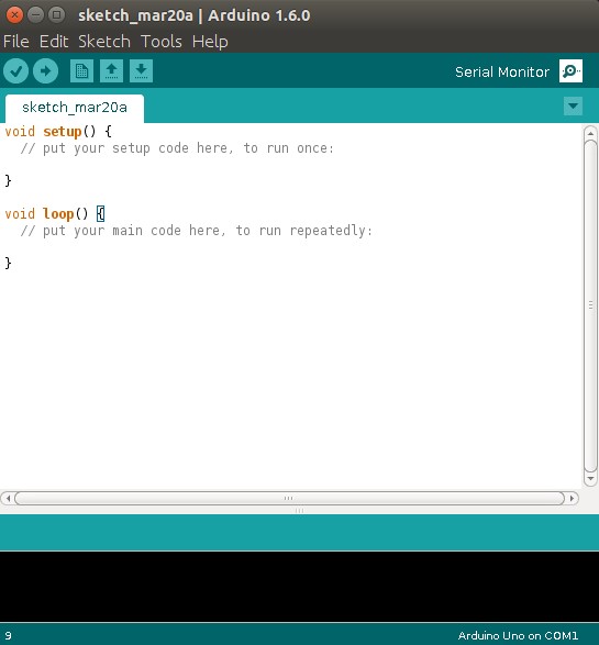
In the second row menu (where the check icon is), you’ll find the commands to compile and upload our developments to the board.
Looking at the code, we have two functions. One is setup, where variables are normally initialized and the loop where the operations are executed as required.
In the File menu we have the option Examples – 01 Basic – Blink. This will display a new window with the code needed to test our LED:
/*

Blink

Turns on an LED on for one second, then off for one second, repeatedly.

This example code is in the public domain.

*/

// Pin 13 has an LED connected on most Arduino boards.

// give it a name:

int led = 13;


// the setup routine runs once when you press reset:

void setup() {

// initialize the digital pin as an output.

pinMode(led, OUTPUT);

}


// the loop routine runs over and over again forever:

void loop() {

digitalWrite(led, HIGH); // turn the LED on (HIGH is the voltage level)

delay(1000); // wait for a second

digitalWrite(led, LOW); // turn the LED off by making the voltage LOW

delay(1000); // wait for a second

}
The example that Arduino generates is quite simple. In line 10 a variable is set with the corresponding pin number on the board. Afterwards, the pin with the variable ‘led’ as an output is initialized. And, in the loop, the LED is turned on and off separated by a delay of one second. Before loading the code to the board, the IDE must be configured so it knows which board and what port we’re using:
Select Tools> Board> Intel Edison
Select Tools> Port> dev / ttyACM0
Now, if the board is properly plugged into the USB port, we can ‘Upload’ the code to the board (Ctrl + U) and we should see our LED turning on and off every second. Amazing! Right?
Now to use the WIFI, we need to work a little harder. Luckily, in the Arduino examples, we have a WIFI section with different alternatives when using networking solutions. Among them are Telnet servers and clients, Web servers and clients and even a Twitter client.
TIP: In our case, for purposes of simplicity, we can use a Web client since we will subsequently send requests to the Orion Context Broker using the HTTP protocol. Note that there are better solutions, but for educational purposes we’ll try to minimize the code as much as possible.
#include <SPI.h>

#include <WiFi.h>

   /**************************/

  /*  Setup configuration  */

/************************/

char ssid[] = "YourWifiSSID";         //  Name of the network

char pass[] = "WifiPassword";        // Network password

char server[] = "130.206.80.47";        // ORION IP address -> Create in https://www.fiware.org/lab/

int status = WL_IDLE_STATUS;   // we predefine the status as On but not connected

int led = 13;        // We initialize a variable to assign the pin number to which the led will be connected

/**

* Arduino Setup configuration

* (Execute only once)

**/

void setup() {

// Inititialization of the Arduino serial port

Serial.begin(9600);

while (!Serial) {

; // wait for serial port to connect. Needed for Leonardo only

}

  // Verify that the board has a WiFi shield

  if (WiFi.status() == WL_NO_SHIELD) {

    Serial.println("Wifi shield is not available");

    // Do not continue with setup, or in other words, stay here forever

    while(true);

  }
The complete code is available in:
https://bitbucket.org/tidchile/ecosystem/src/
FIWARE and Orion Context Broker
As discussed earlier in this tutorial, the Orion Context Broker is a service that based on the OMA NGSI 9/10 standard and can handle sending and receiving contextual information. What does this mean? Primarily, to handle a large number of messages from entities and manage updates, queries, and also handle data subscriptions from the entities. Remember that according to the NGSI 9 and 10 standards, we handle entities as an abstraction of the physical nodes or devices used in IoT solutions.
In the example above, we made an update request to an entity already created. But first let’s review how to work with Orion. A simple way to test the OCB service is to create an account in https://account.lab.fiware.org/ and create a virtual machine with Orion preconfigured in the Cloud section. Alternatively, access Orion’s GitHub site and download a virtual machine to run in our local environment
Another useful tool is a REST client, but we can use cURL if it seems simpler. RESTClient is a client for Firefox that is fairly easy to use.
The configuration aspects of the OCB are outside the scope of this tutorial, as it would require too much detail. Regarding the FIWARE Lab, it is important to note that FIWARE provides virtual machines in the Cloud for free to test FIWARE compontents. You only need to create an account to access the services. Only a quick caveat. As of today (19-03-2015) and temporarily, Spain has no resources available, but there are other regions where VMs can be created.
When we have the necessary tools, the most basic way to interact with the OCB is:
1. Create an entity:
To do this you must take into consideration several factors. Firstly, the call is sent as an HTTP POST request, for example, http://myhost.com:1026/v1/updateContext. By this we mean that we are occupying version 1 of the API with the updateContext operation.
We also have to define several variables in the header of the request:
Accept: application/json
Content-Type: application/json
X-Auth-Token: [TOKEN AUTHENTICATION]
Regarding the token generation, the simplest way is to use python script created by Carlos Ralli on GitHub. A FIWARE account and running the ‘get_token.py‘ script is required.
After setting the header of the request, configure the ‘body’ of the request using the following JSON code:
{

  "contextElements":[

    {

      "type":"LED",

      "isPattern":"false",

      "id":"LED001",

      "attributes":[

        {

          "name":"switch",

          "type":"bool",

          "value":"false"

        }

      ]

    }

  ],

  "updateAction":"APPEND"

}
Here is the structure of a “context Elements” which is a group of entities with certain attributes such as “type“, “isPattern” and “id“. “type” refers to a defined type and allows searching for entities by a particular type. “id” is an attribute that must be unique for each entity to execute searches based on this ID. “IsPattern” will be explained later in point No. 2.
You can also add a number of attributes to the entity in the “attributes” property, where each attribute is defined by “name”, “type” and “value”. Finally, “updateAction” defines whether we will perform an “APPEND” or and “UPDATE”.
If all went well, we will receive a 200 OK response from the server and it will give us the details of the entity created:
{

  "contextResponses" : [

    {

      "contextElement" : {

        "type" : "LED",

        "isPattern" : "false",

        "id" : "LED001",

        "attributes" : [

          {

            "name" : "switch",

            "type" : "bool",

            "value" : ""

          }

        ]

      },

      "statusCode" : {

        "code" : "200",

        "reasonPhrase" : "OK"

      }

    }

  ]

}
2. Consult an entity:
To consult an entity, the standard operation is ‘queryContext’ which would be http://myhost.com:1026/v1/queryContext . We also apply the headers described in point No. 1 and use POST.
The JSON used in the body of the request would be as follows:
{

  "entities":[

    {

      "type":"LED",

      "isPattern":"false",

      "id":"LED001"

    }

  ]

}
This is where you can use “isPattern” in “true” and work either the “type” field or “id” field with regular expressions if we want to execute a slightly more complex search. In the example above we are only looking for the same entity created through the “id”.
There is also a simpler way to do the same query using the following request: GET http://myhost.com:1026/v1/contextEntities/LED001 where LED001 is the “id” of the entity to search for.
3. Update an entity:
This is identical to point No. 1 but changing the “updateAction” attribute from “APPEND” to “UPDATE”.
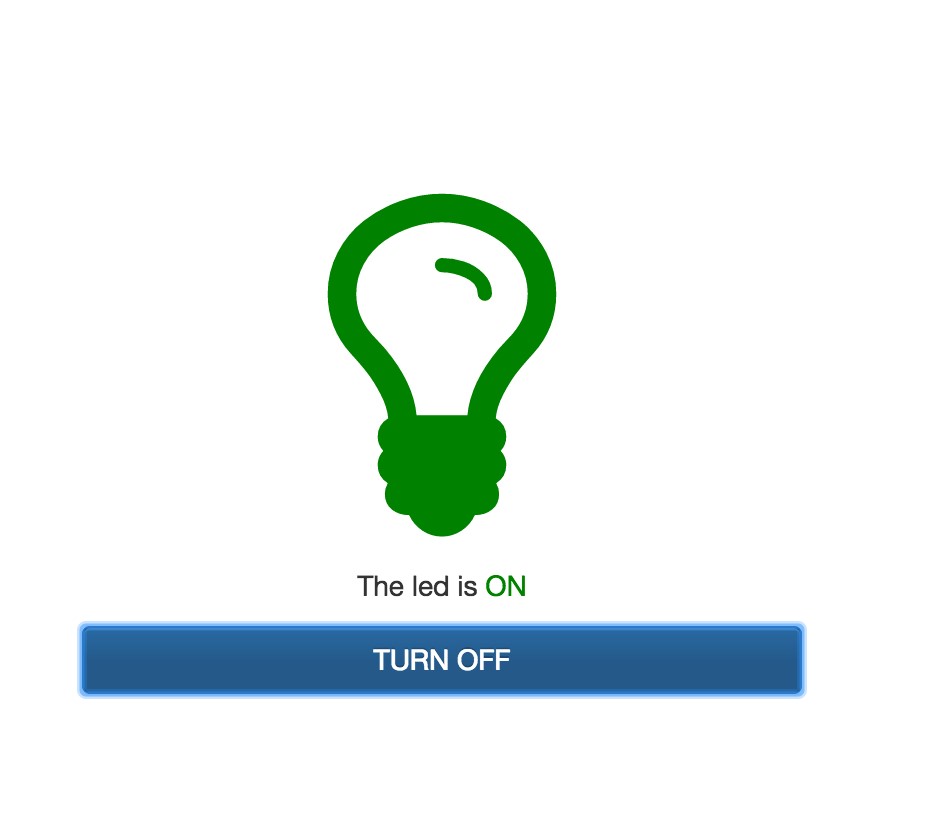
Finally, integrating all that we reviewed, we will be able to generate an action from a simple Web page that can be deployed on a remote server and actually prove that the application’s LED is activated remotely using the OCB.
To do this we will use the LED001 recently created, by setting the ‘switch’ attribute from true to false and vice versa to check the action.
Our web would look like this:
For this, the html code, css and js are shared in: